
Cross-section drawings
Cable cross-section as a drawing, from the data.
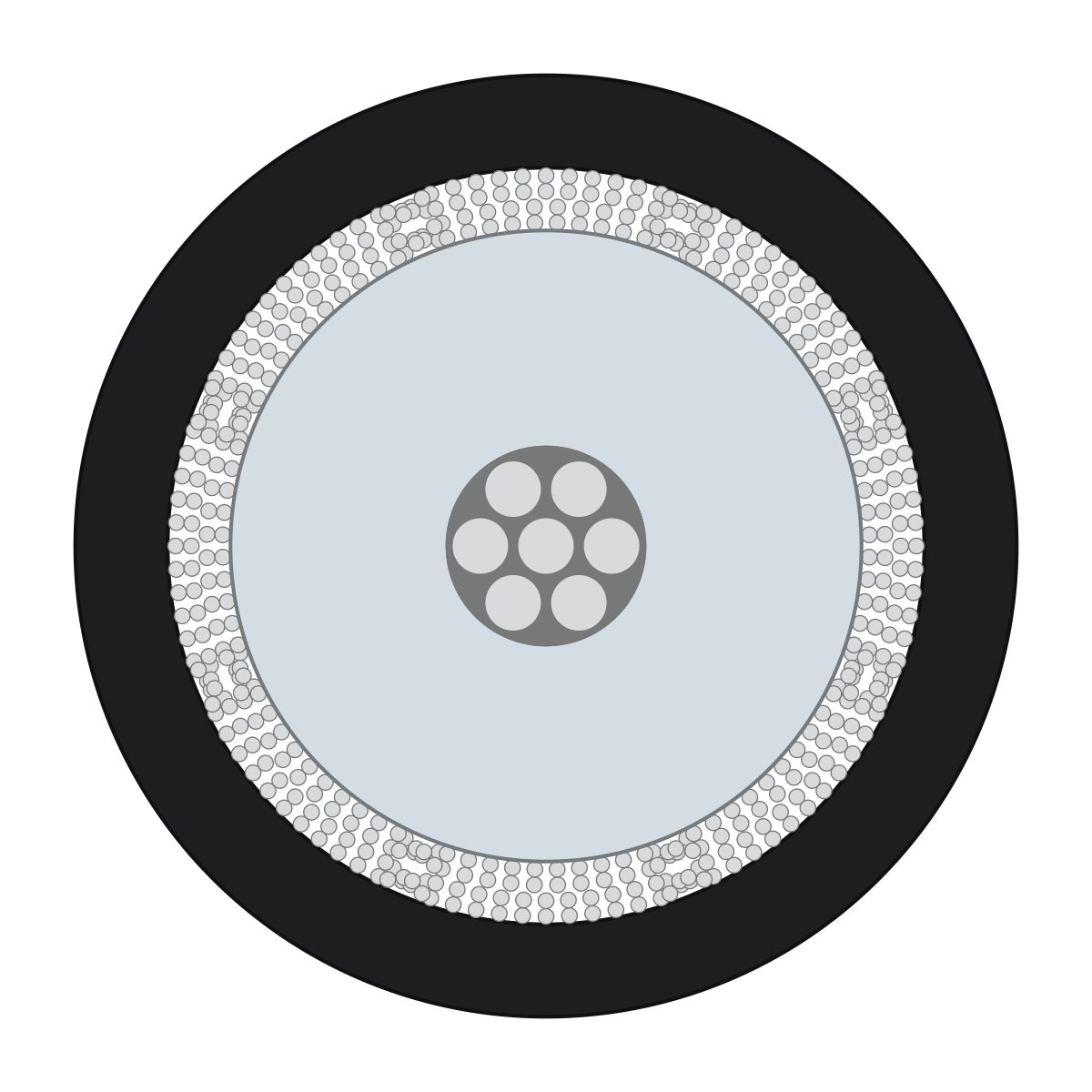
The cross-section drawing shows the cut through the cable to scale and with a legend. It is calculated from the construction data, not drawn on a screen.
Who it's forFor product management, engineering, and marketing at a cable manufacturer.
In short
- 6 drawings per size with a 3D model
- To scale, with a numbered legend
- SVG, PDF, PNG, and DXF
- Ready automatically, no order and no credits
The rendering of a coaxial cable looking at the cable end, and the cross-section drawing of the same cable: the same layers, as an image and as a drawing.

What is a cross-section drawing?
What it is
The cross-section drawing shows the cable cut straight across, to scale and with a numbered legend.
Nobody draws it. The portal calculates it from your cable's construction data, the same numbers behind the 3D model and the images.
That is why every layer is right: its diameter, its count, its place in the cable.
A cable seen from the side, with a dashed line cutting straight across it. An arrow points to the cross-section drawing: jacket, shield, insulation, and conductor as rings.
The cable from the sideThe cut is made hereThe cross-section drawing
Key terms
- Cross-section drawing
- The picture of the cable cut straight across. Every layer in it is drawn to scale.
- Construction data
- Your cable's construction in numbers: which layers it has, how thick they are, and what they are made of.
- Size
- One configuration of a cable type that you can order. Every size with a 3D model has its own drawings.
- Legend
- The numbered list next to the drawing. For each layer, it gives the count, function, and diameter.
- Profile drawing
- The stripped cable end seen from the side, with a label for each layer and a dimension chain.
How is the drawing created?
How it works
You supply the construction data; the portal calculates the drawings on its own, with no order needed.
A drawing is not an order and not an image from the renderer. It is created automatically as soon as the cable is saved.
The process in six stations on one line: you supply the construction data. The portal builds the 3D model and calculates the drawings. You download them and publish the cable. Your customer downloads the drawing from the catalog.
YouThe portalYour customer
YouSupply the data
The portalBuild the 3D model
The portalCalculate the drawings
YouDownload in the portal
YouPublish the cable
Your customerDownload the drawing for free
Step by step
- Step 1 of 6: You
Supply the data
You give us your cable's construction and dimensions: layers, diameters, materials. We use them to set up the cable in the portal.
- Step 2 of 6: The portal
Build the 3D model
The data produces a 3D model for each size. It is the source for images and drawings.
- Step 3 of 6: The portal
Calculate the drawings
After saving, the portal calculates 6 drawings per size. Nobody orders them, and they cost no credits.
- Step 4 of 6: You
Download in the portal
For each size, you download the drawing as SVG, PDF, PNG, or DXF.
- Step 5 of 6: You
Publish the cable
Once the cable is published, the drawing appears on its catalog page. It also appears in the datasheet and in the showcase.
- Step 6 of 6: Your customer
Download the drawing for free
On the catalog page, your customer downloads the drawings as SVG. No account is needed.
What is in the data
A cable is made of layers, from the outside in. Each layer is in the construction data with its dimension and becomes a ring in the drawing.
The construction, layer by layer
- On the outside, the jacket: it protects the cable.
- Below it, the shield: braid or foil against interference.
- Every conductor has its colored insulation.
- Inside, the copper conductors. Exactly as the construction data says.
What is on a drawing?
What you get
You get the cut to scale, the dimensioned outer diameter, and a legend that names every layer.
The image shows the PDF sheet for a coaxial cable. The drawing on it is real: this is how the portal generates it from the data.
2Outer diameter ⌀ 10.8 mm
Legend3
- 1Jacket⌀ 10.8 mm
- 2Braid, outerSilver-plated copper
- 3Braid, innerSilver-plated copper
- 4Insulation⌀ 7.24 mm
- 5ConductorSilver-plated copper · ⌀ 2.26 mm
What the numbers show
The cut
Every layer is drawn at its correct diameter, and every wire of a braid individually.
The outer diameter
It is dimensioned on the drawing. A flat cable shows width and height.
The legend
For each layer: a number, the count, the function, the diameter and, where it is known, the material.
The title block
The PDF sheet lists the cable, size, company, date, and scale.
The scale bar
Use it to check whether the sheet was printed at actual size.
Which of the 6 drawings do I use when?
The styles compared
Color for the catalog and datasheet, black and white or line art for print and technical documents, the profile for the stripped end.
All 6 are ready for every size. You don't have to choose: use the one that fits each purpose.
Three cards showing the same cable: the cut in color, the cut hatched in black and white and as plain lines, and the stripped end seen from the side with a dimension chain.
The construction data of one size
Color
Used forCatalog, datasheet, website
Black and white, and line art
Used forOne-color print, technical documents, manuals
Profile drawing
Used forNotes on stripping and connecting
| Aspect | Color | Black and white, and line art | Profile drawing |
|---|---|---|---|
| Drawings | One: the cut in the cable's colors | Four: hatched, cross-hatched, lines, and shaded lines | One: the stripped end from the side |
| Used for | Catalog, datasheet, website | One-color print, technical documents, manuals | Notes on stripping and connecting |
| Files | SVG, PDF, PNG, and DXF | SVG | SVG |
| Labeling | Numbers and a legend | Numbers and a legend | A name per layer and a dimension chain |
| Scale bar | On the PDF sheet | In the drawing | None: the dimensions are on the chain |
What do I gain, and where are the limits?
Advantages and limits
The drawing is accurate, available immediately, and free, but it cannot be edited by hand.
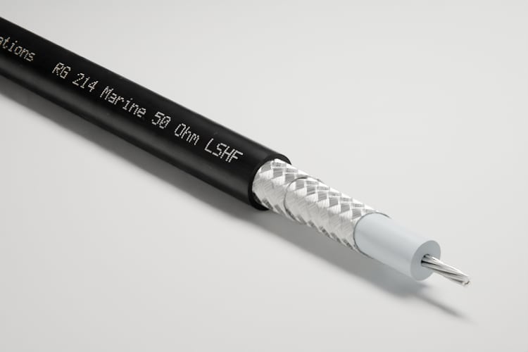
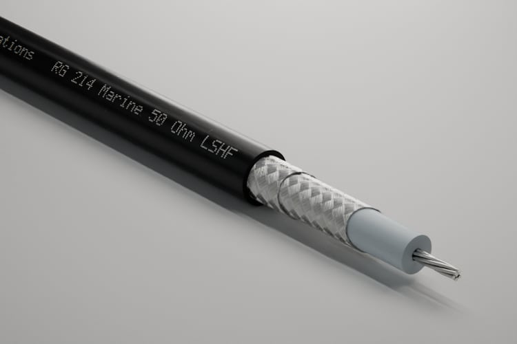
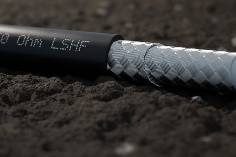
Three cards, each with an image of the cable and the same cross-section drawing: for the catalog, the datasheet, and a showcase. The images change; the drawing stays the same.
- In the catalogOn the cable's page, for download
- In the datasheetAs a vector, sharp at any size
- In a showcaseNext to the images, for one customer


Advantages
It matches the cable
The drawing, the 3D model, and the images come from the same construction data.
Available immediately, no order
The drawings are created automatically after saving and cost no credits.
To scale
The SVG file is set up in millimeters. The PDF sheet picks the largest standard scale that fits, from 50:1 to 1:10.
A style for every purpose
There are 6 drawings per size, from color to plain lines.
For CAD too
The DXF file is set up in millimeters and puts each cable layer on its own CAD layer.
It appears everywhere
The catalog, datasheet, and showcase show the same drawing. You can pull it into your website through the API.
Limits
Nominal dimensions, no tolerances
The drawing shows the nominal cross-section. Tolerances and manufacturing data are not on it.
Nothing by hand
Colors, hatching, and labels are fixed. You can adjust only the end of the profile drawing.
Plastics without material names
The legend names metals and foils by material. It names the jacket and insulation by their function.
PDF, PNG, and DXF for the color drawing only
These files exist only for the color drawing. The DXF file has outlines but no legend.
Only with a 3D model
A size without a model has no drawing. The catalog shows the drawings of the default size.
No longitudinal section
The profile drawing is a schematic side view. It does not show stranding or lay length.
PNG, PDF, and DXF only in the portal
The public catalog offers the drawings as SVG. Only you and your team can download PNG, PDF, and DXF.
Not the right tool if:
- You need a manufacturing drawing with tolerances.
- The drawing needs to use your own colors, drawing frame, or hatching.
- You need the cable as a solid for engineering design, for example as a STEP file.
How is this different from drawing it in CAD?
Compared with today
Drawing by hand is manual work for every size; here the drawing follows the data and changes with it.
Some manufacturers photograph a cut sample instead. That shows a single piece of cable, not the nominal dimension.
A drawing program: circles are drawn one by one with the mouse pointer, from a list of dimensions to type in. By contrast, the table of construction data, which directly produces the finished cross-section drawing.
Until now
Drawn in CAD
Effort per sizeEach drawing individually
From the data
Drawing from the portal
Effort per sizeNone: created on saving
| Aspect | Drawn in CAD | Photo of the cut | Drawing from the portal |
|---|---|---|---|
| Effort per size | Each drawing individually | Saw, grind, and photograph a sample | None: created on saving |
| Matches the data | Only as accurate as it was drawn | A sample, not the nominal dimension | From the same data as the model |
| After a change | Draw again | Photograph again | Recalculated |
| Styles | One; every extra style is more work | One | Every style for every size |
| Scale and legend | Added by hand | Missing | Always included |
| Your own design | Yes, anything is possible | No | No: fixed styles |
What do I need, and what does it cost?
What you need and what it costs
You need your cable and its construction data in the portal; the drawings and their downloads cost no credits.
What you need
Your cable in the portal
The cable must be set up with its construction data. We build it from your documents.
A 3D model per size
Drawings exist for every size that has a model.
A published cable
Only for the public download. The catalog shows the drawing as soon as the cable is published.
No order
You don't have to start anything. The drawings are ready when you open the cable's page.
What it costs
Cross-section drawings cost no credits, neither for the drawing itself nor for its downloads. You pay credits for images and videos.
What else do people ask?
Frequently asked questions
Short answers to the questions people still have about the cross-section drawing.
- Is the cross-section drawing to scale?
- Yes. It is calculated from the diameters in the construction data. The PDF sheet states its scale and has a scale bar.
- Which style comes in which formats?
- All 6 drawings come as SVG. PDF and PNG are made from the color drawing, and the DXF file holds the layer outlines in millimeters.
- Does the legend name the materials?
- For metals and foils, yes. Plastics are usually named by their function, such as insulation or jacket.
- Does the drawing come in German as well?
- Yes. The SVG drawing comes with a German or an English legend. The dimensions in the drawing stay in millimeters.
- What happens when the construction data changes?
- The portal recalculates the drawings. Until the new one is ready, it shows the previous one.
- Can I print all the drawings for my lineup at once?
- Yes. The overview sheet arranges your cables' cross-section drawings side by side on printable pages, in the drawing style you choose.