
RG 174 A/U
Construction and cross-section
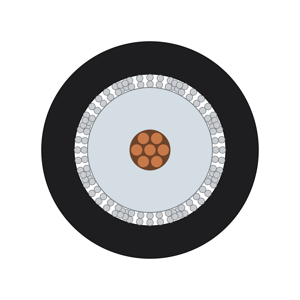
RG 174 A/U is a very thin coaxial cable with a characteristic impedance of 50 ohms: a stranded center conductor of seven copper-clad steel wires, a solid polyethylene dielectric, a braided shield of tinned copper and a black PVC jacket.
Key data
- Characteristic impedance
- 50 Ω
- Outer diameter
- 2.6 mm
- Layers
- 4
Every cable is the answer to a task.
Layer by layer, to scale.
Short, flexible connections where space is tight: inside equipment, at small antennas and as test leads.
inside
Copper-clad steel
Ø 0.48 mm
7 wires
Solid polyethylene (PE)
Ø over this layer 1.5 mm
Tinned copper
Single wire Ø 0.08 mmassumed
PVC
outsideØ 2.6 mm
“Assumed” means: the value does not come from a datasheet but is a usual value or one chosen from a reference.
Cross-section
To scaleOuter diameter
2.6 mm
Dielectric
1.5 mm
Center conductor, stranded
0.48 mm
In the picture, the copper-clad steel wires of the center conductor are shown as copper.

To look for yourself, take it in your hand.
Turn, zoom, hide layers.
RG 174 A/U as a 3D model, from the same data as every picture on this page.
Loads the model (0.1 MB)
3D model3D model · 101 kB
That leaves the question of what the jacket says.
What the name says.
“RG” stands for “Radio Guide” and comes from a US military designation system for radio-frequency cables. The number is a serial number: it says nothing about diameter or characteristic impedance. A letter after the number marks a version of the type, and the suffix “/U” marks general use.
Sources and assumptions
Center conductor, dielectric and the materials of shield and jacket follow the Belden 8216 datasheet. It describes RG 174; the A/U version was not checked separately. The outer diameter comes from a distributor's catalog. The wire diameter of the braid, its number of wires and its lay length are assumed.
- Belden 8216, manufacturer's datasheet
- Rules for using the pictures
- What can be made from a model like this: Product images, Online catalog, Features
Your whole range can look like this.
Our prices are public.
What each package includes, what an image costs as an extra, and how your cables get into the portal.